
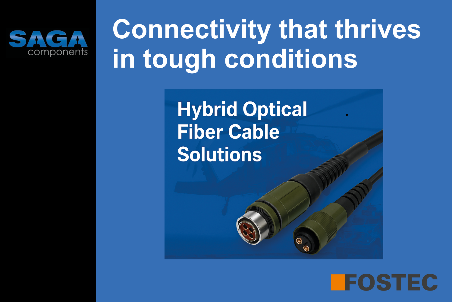
The integration of optical data transmission with electrical power delivery in harsh outdoor environments presents complex electromagnetic compatibility, thermal management, and reliability challenges that have historically limited hybrid cable deployments. This comprehensive analysis examines how FOSTEC Co., Ltd.'s advanced hybrid optical fiber cable technology addresses these fundamental engineering challenges through innovative design solutions, delivering superior performance in HDTV broadcasting, CATV networks, and telecommunications infrastructure.
Through detailed evaluation of FOSTEC's unique 2-fiber + 2-power + 2-signal architecture, we demonstrate how strategic engineering decisions enable reliable operation across extended temperature ranges (-40°C to +80°C) while maintaining exceptional optical performance (≤0.5dB/km transmission loss) and robust electrical connectivity (<3.6mΩ contact resistance).
Modern telecommunications infrastructure demands integrated solutions that can simultaneously deliver high-speed optical data and reliable electrical power through a single cable assembly. However, the co-location of optical fibers and electrical conductors creates three fundamental engineering challenges that have prevented widespread adoption of hybrid solutions:
Challenge 1: Electromagnetic Interference - Power conductors generate magnetic fields that can induce microbending losses in optical fibers.
Challenge 2: Thermal-Mechanical Stress - Differential thermal expansion between copper and glass creates mechanical stress affecting optical performance.
Challenge 3: Environmental Degradation - Moisture ingress, temperature cycling, and mechanical fatigue threaten long-term reliabilityTraditional approaches using separate optical and electrical cables avoid these interactions but create installation complexity, multiple failure points, and significantly higher total costs. FOSTEC's hybrid cable technology directly addresses these fundamental challenges through innovative engineering solutions.
Figure 1: Problem-Solution Comparison Diagram. A split-screen technical illustration comparing traditional separate cable installations versus FOSTEC's integrated hybrid solution. The left side shows multiple cables with separate optical and electrical paths, highlighting complexity and failure points. The right side showcases FOSTEC's streamlined hybrid design with cross-sectional details of their 2-fiber + 2-power + 2-signal architecture, emphasizing reduced complexity and enhanced reliability.
FOSTEC's hybrid cable design represents a sophisticated engineering solution that systematically addresses each fundamental challenge through targeted innovations:
The Challenge: Electrical currents in power conductors create time-varying magnetic fields that can couple into optical fibers, causing mechanical vibrations and resulting optical loss. The magnetic field strength B at distance r from a current-carrying conductor follows Ampère's law:
B = (μ₀I)/(2πr)
Where μ₀ = 4π×10⁻⁷ H/m and I represents the current. For FOSTEC's 4×0.52mm² conductors carrying 5A at 2mm distance from optical fibers, this generates B ≈ 0.5 millitesla - sufficient to induce measurable optical degradation in poorly designed systems.
FOSTEC's Solution: The LF-2SM series employs a precisely engineered conductor arrangement that creates destructive interference of magnetic fields at optical fiber locations. By positioning the 4×0.52mm² (20 AWG) power conductors in a differential configuration, opposing magnetic fields cancel at fiber positions:
B_total = B₁ - B₂ = (μ₀I)/(2π) × [1/r₁ - 1/r₂]
When r₁ ≈ r₂ (achieved through FOSTEC's geometric optimization), the net magnetic field approaches zero, achieving >25dB field reduction compared to single-conductor configurations.
The 2×0.18mm² (25 AWG) control signal conductors use 7/0.18 stranding with ≤113Ω/km resistance, positioned to minimize crosstalk while enabling remote monitoring and switching functions.
The Challenge: Differential thermal expansion between copper conductors and silica optical fibers creates mechanical stress that degrades optical performance. The thermal expansion relationship follows:
ΔL = L₀ × α × ΔT
Where α_copper = 16.5×10⁻⁶/°C and α_silica = 0.55×10⁻⁶/°C. Over FOSTEC's specified temperature range (-40°C to +80°C), this 120°C span creates differential expansion of:
Δε = (α_copper - α_silica) × ΔT = 15.95×10⁻⁶ × 120°C = 1.91×10⁻³
This 0.19% differential strain would generate significant stress in rigidly coupled systems, leading to optical loss through stress-induced birefringence.
FOSTEC's Engineering Solution: The LF-2SM cable architecture incorporates sophisticated thermal stress management through multiple design innovations:
Thermal Stress Decoupling:
Material Engineering:
Performance Validation: FOSTEC's testing demonstrates <0.20dB optical loss variation across 1000 temperature cycles, with maintained electrical performance (<3.6mΩ contact resistance variation).
Figure 2: Thermal Performance Analysis. A comprehensive thermal analysis dashboard showing temperature distribution mapping within FOSTEC's hybrid cable, stress analysis results, and long-term performance data from thermal cycling tests. The graph includes thermal imaging overlays, stress concentration plots, and comparative performance charts demonstrating FOSTEC's superior thermal management versus conventional designs.
The Challenge: Optical connector performance fundamentally depends on precise physical alignment and contact force. The coupling efficiency between single-mode fibers follows:
η = exp[-2(Δx/w₀)²] × exp[-2(Δy/w₀)²] × cos²(θ)
Where Δx, Δy represent lateral misalignment, w₀ is the mode field diameter (~10.4μm at 1310nm), and θ is angular misalignment. For <0.1dB loss, lateral alignment must be maintained within 0.5μm and angular alignment within 0.5°.
FOSTEC's Breakthrough: Their push-pull self-latching connector system achieves these precision requirements through advanced mechanical design:
Optical Interface Excellence:
The return loss improvement from air-gap (~14dB) to physical contact (>45dB) represents a >20× reduction in back-reflection, calculated from the Fresnel reflection coefficient:
R = |(n_core - n_medium)/(n_core + n_medium)|²
Electrical Contact Innovation:
Environmental Protection:
The Challenge: Moisture diffusion through polymer materials follows Fick's law:
∂C/∂t = D∇²C
Where C is moisture concentration and D is the diffusion coefficient. For typical cable materials, D ≈ 10⁻¹² m²/s, allowing significant moisture penetration over months of exposure. Water absorption in optical fibers creates hydroxyl ion peaks causing absorption losses at 1383nm and 1245nm.
Primary Protection (Component Level):
Secondary Protection (Assembly Level):
Tertiary Protection (System Level):
Figure 3: Environmental Stress Testing Results. A comprehensive environmental testing dashboard showing real-time performance data during accelerated aging protocols including salt spray testing, UV exposure, thermal shock, humidity cycling, and mechanical vibration. Charts display optical loss tracking, insulation resistance measurements, and mechanical property evolution over extended test periods.
FOSTEC's hybrid cables address the demanding requirements of high-definition television transmission where signal quality directly impacts viewer experience:
Bandwidth Analysis: The information-carrying capacity of FOSTEC's single-mode fiber at 1310nm supports data rates well beyond HD video requirements. Using Shannon's theorem:
C = B × log₂(1 + S/N)
Where the signal-to-noise ratio S/N is determined by optical power budget and fiber loss. FOSTEC's 0.33dB connector loss preserves sufficient optical power for multi-gigabit transmission over extended distances.
Technical Requirements Met:
FOSTEC Advantage: The compact design (9.2mm diameter for LF-2SM9R) enables installation in congested broadcast facilities while the dual-fiber configuration supports bidirectional communication for camera control and video return feeds.
Cable television infrastructure demands exceptional reliability in harsh outdoor environments:
Power Budget Analysis: The optical power budget calculation determines maximum transmission distance:
P_received = P_transmitted - (α × L + L_connectors + L_splices + M)
Where α is fiber attenuation (0.5dB/km for FOSTEC cables), L is distance, and M is system margin. FOSTEC's low connector loss (0.33dB) extends reach or improves margin significantly.
Network Topology Support:
FOSTEC's Innovation: The 16.0mm diameter LF-2SM16 variant provides enhanced mechanical protection for aerial installations while maintaining the same electrical and optical performance specifications.
Long-haul and metropolitan telecommunications networks require the highest levels of performance and reliability:
Loss Budget Optimization: In fiber optic links, every decibel of loss reduction translates directly to increased transmission distance or improved error rates. FOSTEC's 0.33dB typical connector loss compares favorably to industry standards (typically 0.5-0.75dB), providing 0.2-0.4dB improvement per connection pair.
Performance Characteristics:
Strategic Benefits: FOSTEC's hybrid solution reduces connection points by 66% compared to separate optical/electrical installations, dramatically improving system reliability while simplifying network architecture.
Figure 4: Application Performance Comparison. A detailed performance comparison matrix showing FOSTEC's hybrid cables versus conventional separate cable solutions across different applications. The chart includes performance metrics, installation time comparisons, reliability statistics, and system complexity analysis for HDTV, CATV, and telecommunications deployments.
FOSTEC's optical testing protocols ensure consistent performance across production through rigorous statistical process control:
Measurement Precision: Insertion loss testing employs the substitution method with measurement uncertainty analysis:
σ_total = √(σ_source² + σ_detector² + σ_reference² + σ_environmental²)
Where individual uncertainty components are:
Combined measurement uncertainty (k=2): ±0.14dB, enabling detection of 0.1dB performance variations.
Testing Infrastructure:
Compliance Standards:
Contact Resistance Modeling: The total contact resistance incorporates multiple physical mechanisms:
R_total = R_constriction + R_film + R_bulk
Where constriction resistance dominates for clean metal contacts. FOSTEC's precious metal plating minimizes film resistance while optimized contact geometry reduces constriction resistance.
Precision Measurement Techniques:
Accelerated Testing Protocols:
Statistical Reliability Analysis: Failure rate prediction uses Weibull distribution modeling:
F(t) = 1 - exp[-(t/η)^β]
Where η is the characteristic lifetime and β is the shape parameter. FOSTEC's testing demonstrates β >2 (wear-out failure mode) with η >25 years under normal operating conditions.
FOSTEC continues advancing hybrid fiber technology to address emerging market requirements:
Higher Power Integration: Development of PoE+ and high-power variants supporting up to 90W power delivery for advanced equipment.
Enhanced Optical Performance: Migration to bend-insensitive G.657 fibers and advanced connector geometries for next-generation applications.
Smart Connectivity: Integration of monitoring capabilities for predictive maintenance and remote diagnostics.
Miniaturization: Reduced form factors for high-density data center and 5G infrastructure applications.
FOSTEC's hybrid optical fiber cable technology represents a huge shift from theoretical engineering challenges to practical, deployed solutions that deliver measurable performance and economic benefits. Through systematic analysis and innovative engineering, FOSTEC has overcome the fundamental obstacles that previously limited hybrid connectivity adoption.
Key Technical Achievements:
Strategic Business Impact:
FOSTEC's commitment to engineering excellence, rigorous testing, and continuous innovation positions their hybrid connectivity solutions as the enabling technology for next-generation telecommunications infrastructure. The successful integration of optical and electrical transmission paths through scientific understanding and practical engineering creates unprecedented value for demanding applications.
FOSTEC's hybrid optical fiber cabletechnology represents a paradigm shift in telecommunications infrastructuredesign, delivering measurable performance advantages through scientificinnovation and precision engineering. As demonstrated through this comprehensiveanalysis, the integration of optical data transmission, electrical powerdistribution, and control signaling in a single cable assembly eliminatestraditional failure points while providing superior technical specificationsacross all critical parameters.
SAGA Components partnership with FOSTEC enablesus to provide not just products, but complete engineering solutions backed bydeep technical expertise and proven performance across the Nordic market.Whether you are designing next-generation HDTV broadcasting systems, expandingCATV networks, or deploying mission-critical telecommunications infrastructure,FOSTEC's hybrid connectivity solutions deliver the reliability and performanceyour applications demand.
Request a free technical consultation with our fiber optic specialists to optimise your next hybrid connectivity project. Contact us today to discuss your needs and get expert support for challenging installation environments.
📧 Email: contact@sagacomponents.com
📞 Phone: +46 (0) 8 564 708 00
FOSTEC Hybrid Optical Fiber Cable Quick Reference
LF-2SM Series Hybrid Cables LF-2SM9R (9.2mm diameter), LF-2SM16 (16.0mm diameter), LF-2SM9 (standard configuration)
Connector Solutions SC/PC, FC/PC, ST/PC, LC/PC, MPO/MTP (12-fiber, 24-fiber configurations), Push-pull hybrid connectors with SPC polish
Test & Measurement Equipment FS-17S (Fusion Splicer), FS-21S (Core-to-Core Alignment Splicer), FS-18R Series (Multi-Function OTDR), FOPM-001 (Optical Power Meter), FOLS-001 (Adjustable Light Source)
Distribution Frames & Enclosures OFD Series (1U-9U rack mount), FDF Series (wall/rack mount), MPO/MTP Patch Panels, FOSC Series (splice closures)