
Modern military electronics face an increasingly challenging paradox: systems must deliver greater functionality while occupying less space and weight. From soldier-worn systems to unmanned aerial vehicles (UAVs), guided munitions, and satellite payloads, the demand for miniaturization has never been more critical. Traditional interconnect solutions, even ruggedized military-specification connectors like those meeting MIL-DTL-32139 (Micro-D), often represent a significant bottleneck in achieving the required size, weight, and power (SWaP) targets.
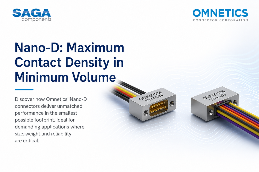
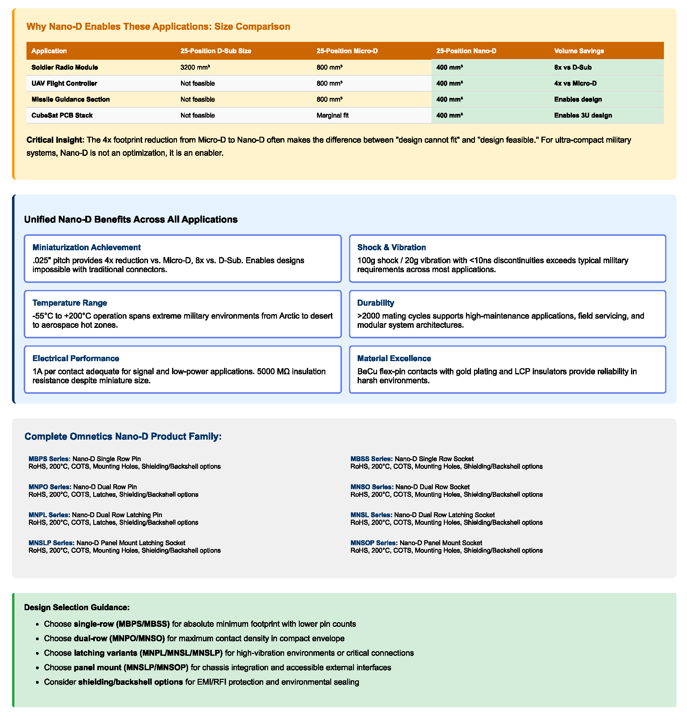
Omnetics Connector Corporation's Bi-Lobe®/Nano-D connector family addresses this challenge through a fundamental reimagining of connector architecture at the .025" pitch level. These connectors achieve 4x miniaturization compared to standard Micro-D connectors and 8x reduction compared to previous D-Sub footprints, while maintaining or exceeding the reliability requirements demanded by defense and aerospace applications. This article examines the technical architecture, material science, and engineering challenges solved by Nano-D connectors, with specific focus on military electronics applications where space constraints directly impact mission capability.
Note: As a franchised distributor, SAGA Components, via Jørgensen & Co., provides sales and support for Omnetics products exclusively in Denmark.
Military electronics designers face severe space limitations across multiple platforms. Soldier-worn systems must integrate power supplies, processors, communications equipment, sensors, and user interfaces within form factors compatible with tactical gear. UAVs, particularly small tactical drones and loitering munitions, allocate precious volume to propulsion, fuel, sensors, and processing, thus leaving minimal space for interconnects. Guided projectiles and artillery munitions must fit electronics within existing mechanical envelopes while surviving launch accelerations exceeding 15,000 g.
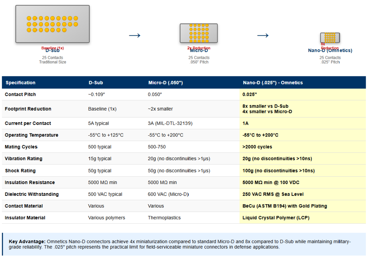
Traditional connector technologies impose significant size penalties. A standard 25-position D-Sub connector occupies substantial board real estate and adds considerable height to electronics assemblies. Even Micro-D connectors at .050" pitch, while substantially smaller than D-Sub, still consume space that designers increasingly cannot afford.
The challenge extends beyond simple geometric miniaturization. Military electronics require high contact density to support complex signal routing, but each contact must maintain adequate current-carrying capacity. Standard Micro-D contacts carry 3 AMPs per contact, but this capability comes with the larger .050" pitch. Reducing pitch typically forces proportional reductions in conductor cross-sectional area, potentially limiting current capacity and creating thermal management challenge.
Additionally, reduced contact spacing raises concerns about voltage withstanding capability, insulation resistance, and dielectric breakdown, all critical parameters in military systems that may operate across wide voltage ranges and in harsh environmental conditions including high humidity, salt fog, and fluid contamination.
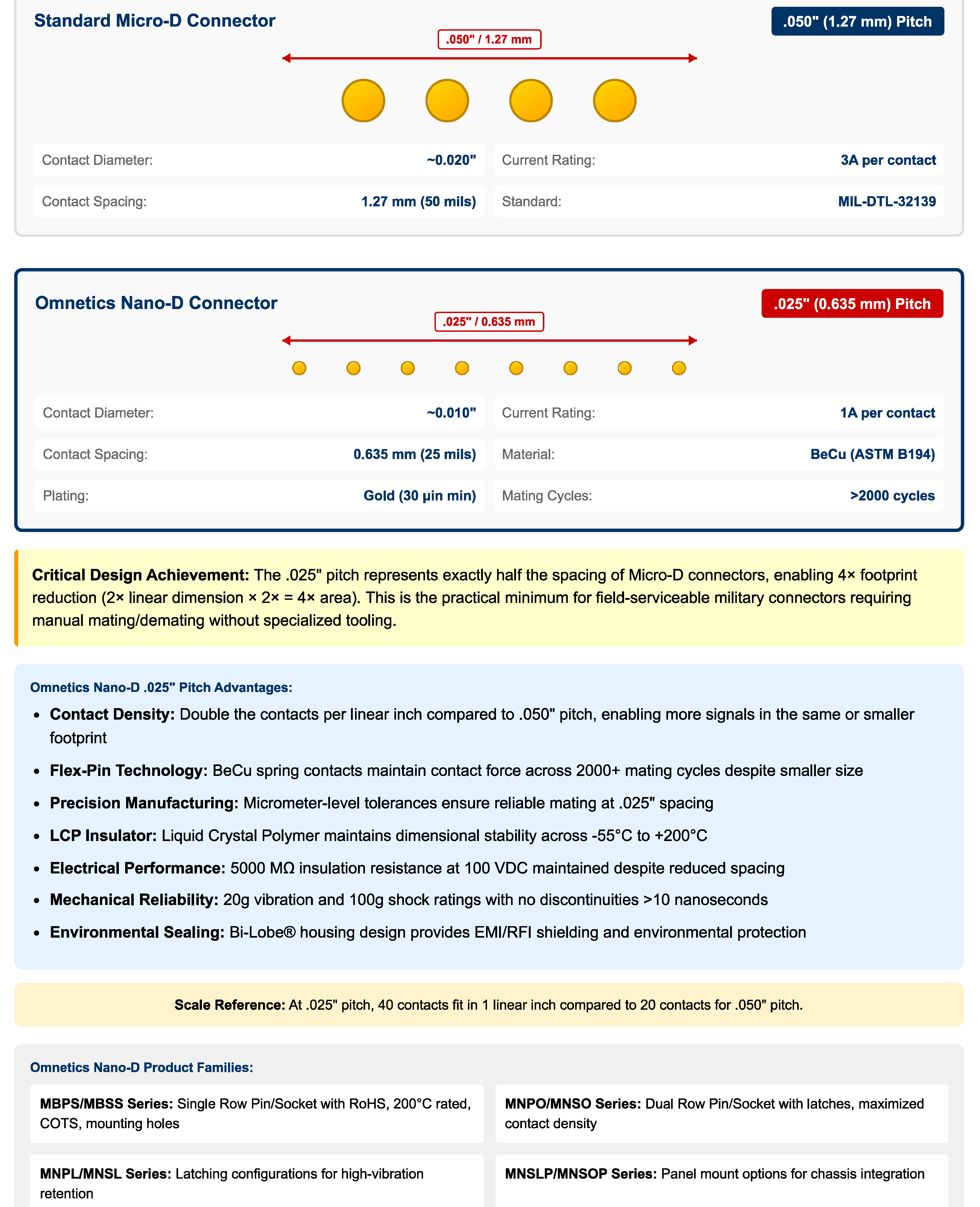
Omnetics Bi-Lobe®/Nano-D connectors achieve their miniaturization through a precise .025" pitch—exactly half the .050" pitch of standard Micro-D connectors. This geometric reduction directly translates to a 4x reduction in the footprint required for a given contact count. The .025" pitch represents the practical limit for reliable hand assembly and field maintenance while maintaining the mechanical robustness required for military applications.
The .025" pitch architecture requires precision manufacturing tolerances in contact positioning. Omnetics manufactures Nano-D contacts with positional accuracy measured in micrometers to ensure reliable mating cycles. The tighter pitch demands exceptional dimensional control throughout the manufacturing process, from contact stamping to insulator molding to final assembly.
The distinctive "lobed" housing of Nano-D connectors serves multiple engineering functions beyond simple mechanical protection. The housing geometry provides integrated EMI/RFI shielding through complete contact enclosure in the mated condition. The bi-lobe configuration allows for optimized contact arrangement, supporting both single-row and dual-row configurations while maintaining compact overall dimensions.
The Omnetics’ Nano-D connectors are available in several configurations:
The dual-row configurations (MNPO and MNSO Series) maximize contact density within the minimal footprint, critical for applications requiring numerous signal paths.
Nano-D connectors utilize Omnetics' proprietary flex-pin contact design with gold plating. Unlike solid-pin contacts found in many military connectors, the flex-pin architecture employs a spring-characteristic contact stamped from beryllium copper (BeCu) conforming to ASTM B194. This material selection provides optimal combination of electrical conductivity, spring properties, and durability.
The flex-pin design features a compliant beam structure that deflects during mating, creating controlled contact force without requiring the mass and volume of separate spring elements. This compliance accommodates minor misalignment during mating and maintains contact force across temperature cycling and vibration. The gold plating provides low contact resistance and protects against fretting corrosion, which is a critical failure mode in high-vibration military environments.
Omnetics' Nano-D connectors achieve over 2,000 mating cycles durability, exceeding the requirements of many military applications where frequent connection/disconnection occurs during maintenance, system reconfiguration, or field repair.
The insulator material fundamentally determines a connector's electrical performance and environmental resistance. Nano-D connectors employ liquid crystal polymer (LCP) insulators, representing advanced thermoplastic technology optimized for demanding applications.
LCP offers several advantages for miniature military connectors:
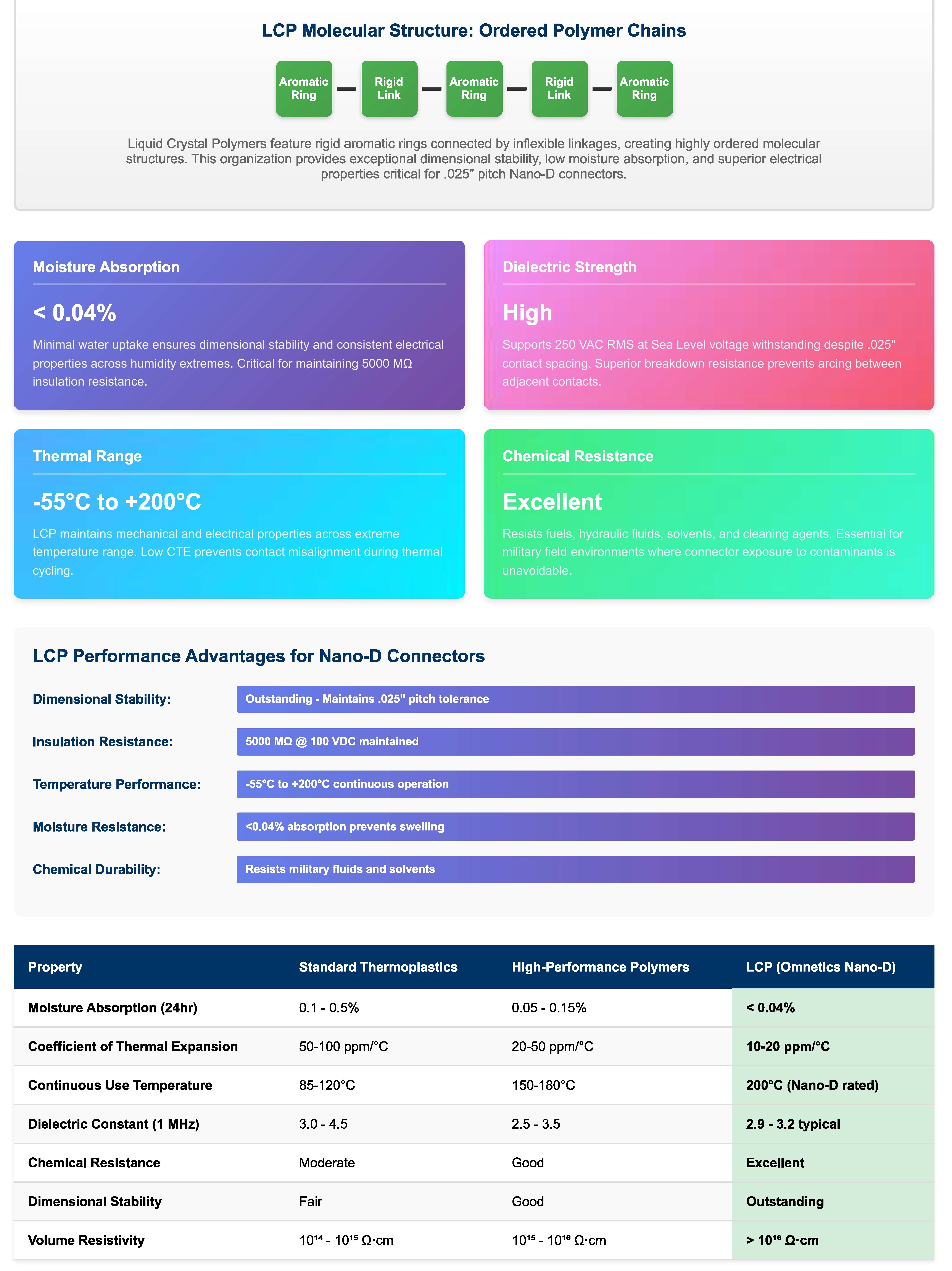
The LCP insulator design incorporates precise cavities for each contact, maintaining the .025" pitch with positional accuracy throughout the operating temperature range. This dimensional stability proves critical for achieving the specified 5000 Megohms minimum insulation resistance at 100 VDC, even in humid environments.
Despite the 4x reduction in size compared to Micro-D, Nano-D connectors maintain 1 AMP per contact current capacity, tat is adequate for most signal applications and many power distribution requirements in military electronics. This capacity stems from careful optimization of contact cross-sectional area, material selection, and thermal management.
The current-carrying capacity calculation involves several factors:
I = A × J
Where:
• I = current carrying capacity (Amperes)
• A = conductor cross-sectional area (mm²)
• J = current density (A/mm²)
For Nano-D contacts at 1 AMP, the BeCu contact material provides sufficient conductivity while maintaining the spring properties required for reliable mechanical performance. The gold plating, while thin (typically 30 micro-inches minimum per Omnetics specifications), contributes minimal resistance while providing oxidation protection critical for long-term reliability.
Current flow through any conductor generates resistive heating according to:
P = I² × R
Where:
• P = power dissipation (Watts)
• I = current (Amperes)
• R = contact resistance (Ohms)
At 1 AMP per contact, proper thermal design becomes essential, particularly in high-contact-count configurations. Nano-D connectors address thermal management through several mechanisms:
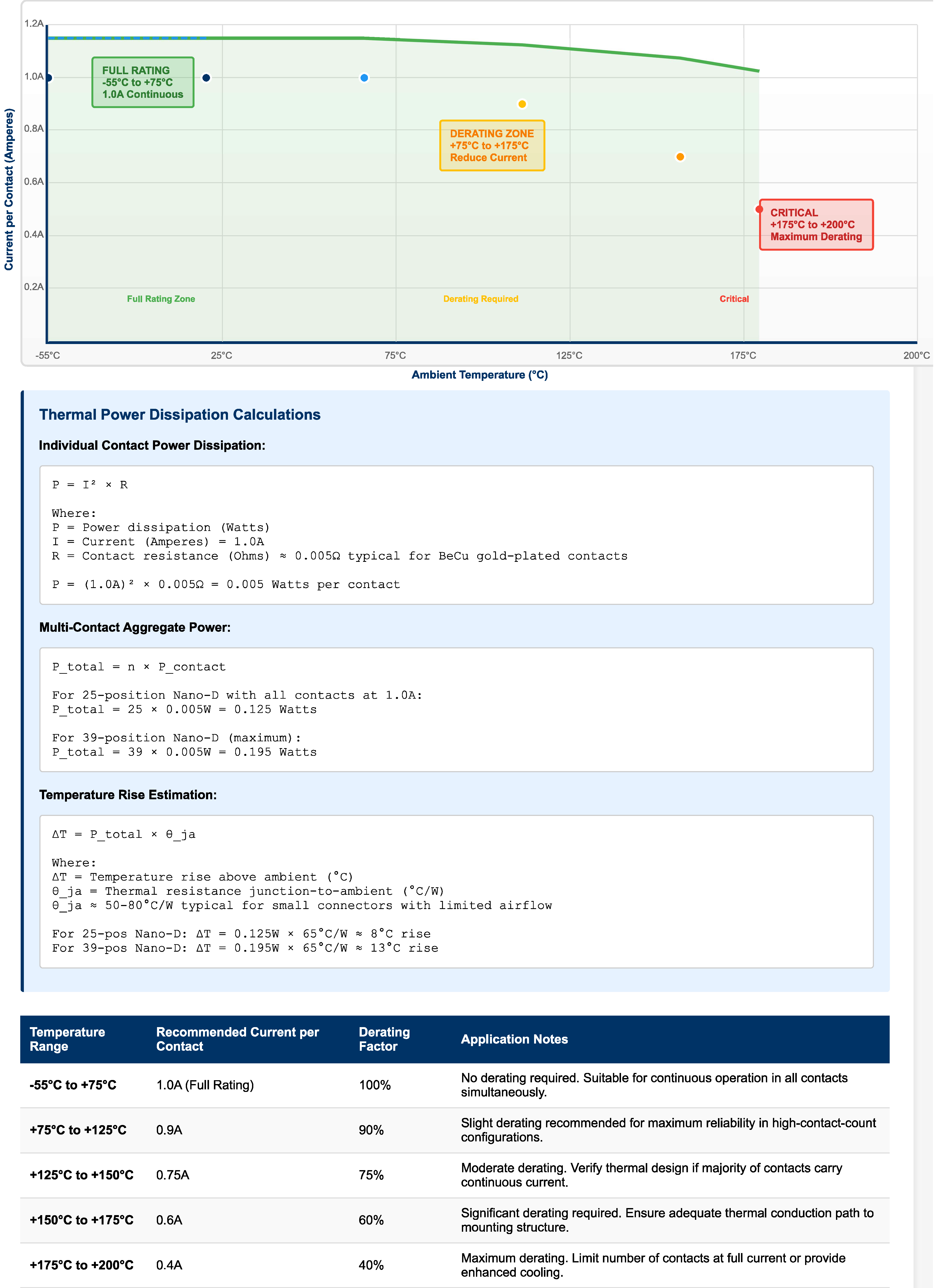
In practice, designers must consider not only individual contact current but also aggregate power dissipation across all contacts. A 25-position Nano-D connector with all contacts carrying 1 AMP continuous must dissipate the cumulative thermal load while maintaining contact temperatures within material limits.
The .025" pitch raises important questions about voltage withstanding capability. Omnetics specifies 250 VAC RMS at Sea Level dielectric withstanding for Nano-D connectors, achieved through the combination of LCP insulator properties and precise contact positioning.
Dielectric breakdown in air follows approximately Paschen's curve, with breakdown voltage dependent on pressure and gap distance. At the .025" pitch (0.635 mm), proper insulator geometry prevents direct air gaps between adjacent contacts, forcing potential breakdown paths through the high-dielectric-strength LCP material.
The specified 5000 Megohms minimum insulation resistance at 100 VDC ensures minimal leakage current between adjacent contacts, critical for analog signal integrity and power distribution applications. This specification remains valid across the operating temperature range, demonstrating the stability of LCP insulator material properties.
Military electronics experience severe mechanical environments. Artillery-launched projectiles encounter launch accelerations exceeding 15,000 g. Airborne platforms experience continuous vibration across wide frequency ranges. Ground vehicle electronics endure shock loads from rough terrain and blast effects.
Omnetics specifies Nano-D connector performance as:
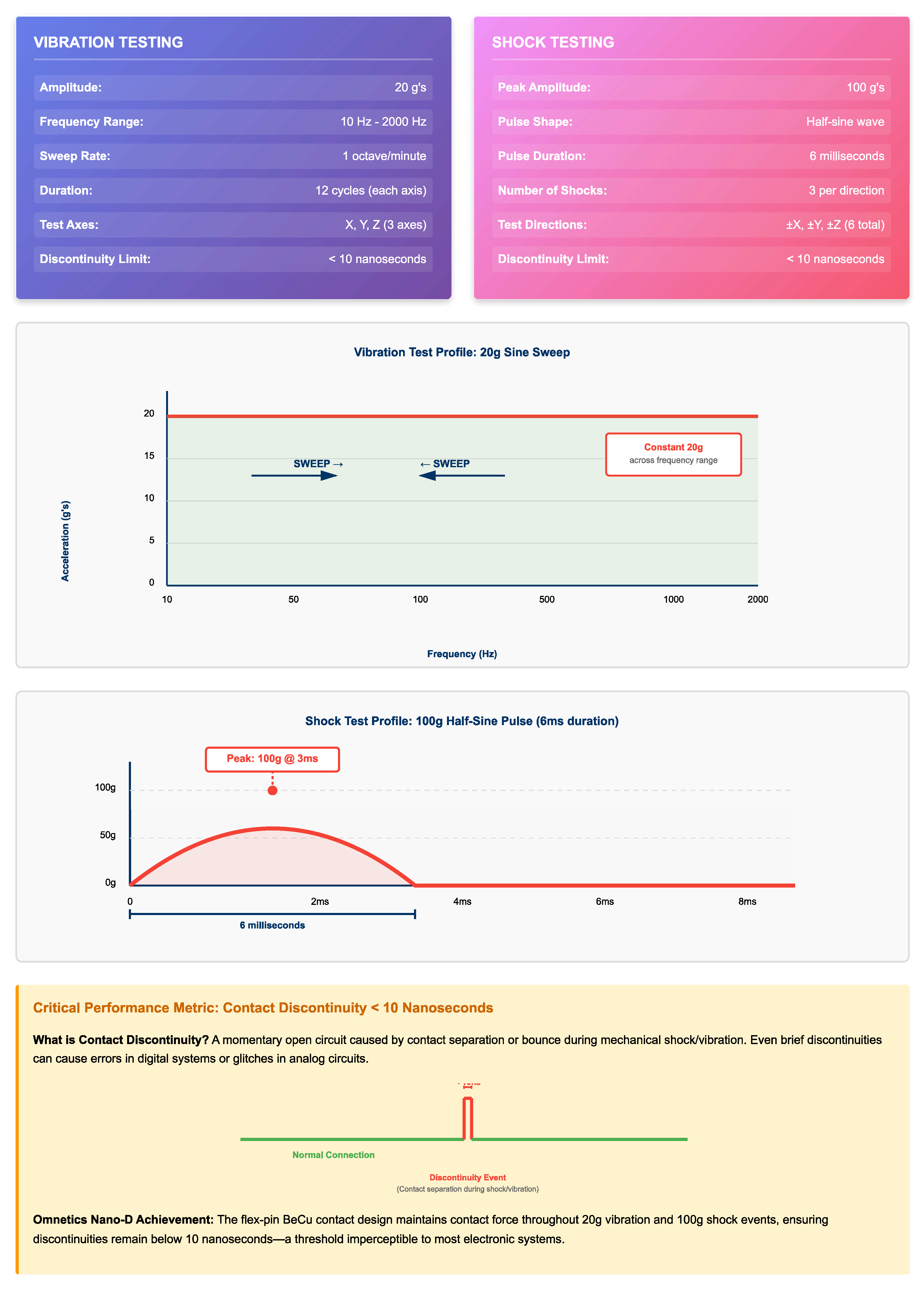
These specifications refer to contact discontinuities, that is momentary open circuits caused by contact separation under dynamic loading. The 10-nanosecond threshold represents the practical limit for signal disruption that might cause errors in high-speed digital systems or glitches in analog circuits.
The flex-pin contact design proves critical for shock/vibration performance. Unlike rigid pin contacts that rely on socket spring force, the compliant flex-pin maintains contact through mechanical deflection, accommodating relative motion between mated connectors without separation. The BeCu material provides the spring memory required to maintain contact force across millions of vibration cycles.
Omnetics specifies that Nano-D connectors exceed 2000 mating cycles, substantially higher than typical requirements for most military applications. This durability stems from several design features:
For latching variants (MNPL and MNSL Series with Nano-D Dual Row Latching configurations), the mechanical retention system withstands the specified mating cycle count without degradation, ensuring reliable connection retention in high-vibration environments.
Modern soldier systems integrate communications, computing, power management, and sensors within form factors compatible with tactical gear. Every cubic centimeter and gram directly impacts soldier mobility and endurance. Nano-D connectors enable:
The 200°C temperature rating provides margin for connectors located near electronic components generating significant heat, that is common in soldier systems where compact packaging limits airflow for cooling.
Small tactical UAVs and loitering munitions represent extreme examples of space-constrained military electronics. These platforms allocate volume to propulsion, fuel, flight control surfaces, sensors, and payload, thus leaving minimal space for interconnects between subsystems.
Nano-D connectors address UAS requirements through:
The 20 g vibration specification proves particularly relevant for UAS applications, where propeller/rotor vibration and aerodynamic buffeting create continuous high-frequency mechanical loading.
Guided projectiles and artillery rounds present perhaps the most severe environment for electronics and interconnects. Launch accelerations may exceed 15,000 g, temperatures during propellant ignition spike rapidly, and mechanical shock loads from gun barrel rifling and muzzle blast stress every component.
While Nano-D's 100 g shock specification falls short of direct gun-launch requirements (which typically require potting or epoxy encapsulation of all electronics), these connectors serve critical roles in:
The exceed-2000-mating-cycles durability supports munitions that undergo multiple test/handling cycles before deployment.

Small satellites, particularly CubeSats and nanosatellites, face extreme volume constraints. Every connector represents significant fractional volume in a 10cm × 10cm × 10cm or smaller spacecraft. Nano-D connectors enable:
The -55°C to +200°C operating temperature range accommodates on-orbit thermal cycling, while the LCP insulator's low outgassing properties (necessary for space applications, though specific outgassing data should be confirmed with Omnetics for mission-critical applications) support vacuum environments.
Designers must select between single-row (MBPS/MBSS Series) and dual-row (MNPO/MNSO/MNPL/MNSL Series) configurations based on application requirements. Single-row configurations provide the absolute minimum footprint for lower contact counts, while dual-row designs maximize density for higher pin counts within compact envelope.
The choice between standard and latching variants (MNPL/MNSL Series) depends on connector accessibility and retention requirements. Latching designs provide positive mechanical retention for connections in high-vibration environments or where accidental disconnection would compromise mission success.
Operating multiple contacts at or near the 1 AMP rating requires careful thermal analysis. Designers should:
For applications near the 200°C upper temperature limit, derating current capacity provides reliability margin.
The Bi-Lobe® metal housing provides inherent EMI/RFI shielding for enclosed contacts. For applications requiring additional protection, Omnetics offers shielding/backshell options for most Nano-D series. Proper cable shielding termination at the backshell ensures continuous shield path from cable through connector to equipment chassis, critical for maintaining electromagnetic compatibility (EMC) in military systems operating in dense electromagnetic environments.
The .025" pitch requires precise alignment during mating to prevent contact damage. Housing designs incorporate alignment features, but designers should ensure that:
Omnetics manufactures Nano-D connectors as COTS (Commercial Off-The-Shelf) products with RoHS compliance. The 200°C rating and durability specifications exceed requirements of many military applications. While Nano-D connectors do not directly qualify to traditional MIL-DTL specifications (Micro-D meets MIL-DTL-32139), their performance specifications position them for military applications where miniaturization drives design decisions and COTS acquisition provides schedule and flexibility advantages.
For space applications, designers should review specific mission requirements regarding outgassing, thermal vacuum cycling, and radiation tolerance, consulting with Omnetics engineering for application-specific qualification data.
Omnetics Bi-Lobe®/Nano-D connectors represent a fundamental advancement in miniature interconnect technology for military electronics. The .025" pitch architecture achieves 4x reduction in footprint compared to Micro-D and 8x compared to D-Sub, while maintaining 1 AMP per contact current capacity and achieving over 2000 mating cycles durability. The combination of flex-pin BeCu contacts, liquid crystal polymer insulators, and bi-lobe housing design delivers performance specifications matching or exceeding traditional military connector requirements across shock (100 g), vibration (20 g), temperature (-55°C to +200°C), and voltage withstanding (250 VAC RMS).
Product families including MBPS/MBSS Series (single-row), MNPO/MNSO Series (dual-row), and MNPL/MNSL/MNSLP Series (latching configurations) provide design flexibility for applications from soldier-worn systems to UAVs, guided munitions, and satellites. As military electronics continue demanding greater functionality in smaller packages, Nano-D connectors provide enabling technology for next-generation defense systems where traditional interconnects present unacceptable size and weight penalties.
Navigating the complexities of miniature connector selection, space-constrained integration, and military-grade reliability requirements demands specialized knowledge. As a leading Nordic distributor of electronic components and solutions, our technical team provides comprehensive support in partnership with Omnetics Connector Corporation for customers based in Denmark. We help you:
By partnering with our team and leveraging Omnetics' comprehensive Nano-D connector portfolio, you can develop miniaturized, ruggedized, and mission-reliable interconnect solutions for the most demanding military and aerospace applications.
Note: As a franchised distributor, SAGA Components, via Jørgensen & Co., provides sales and support for Omnetics products exclusively in Denmark.
Technical Disclaimer
Important Notice Regarding Product Specifications and Technical Content
This technical article has been prepared for informational and marketing purposes to illustrate the engineering considerations relevant to high-reliability miniature connectors in space-constrained military, aerospace, and defense applications.
While the specifications, product series (e.g., MBPS, MNPO, MNSL Series), and performance data referenced herein are drawn directly from Omnetics Connector Corporation's published product catalog ("Short Form Catalog"), certain technical discussions regarding engineering principles (such as thermal management, dielectric properties, or materials science) represent generalized industry knowledge. These discussions are intended to provide context for the catalog specifications and may not reflect Omnetics' specific proprietary design data or internal testing methodologies.
All numerical specifications (e.g., 100 g shock, 20 g vibration, 1 AMP current capacity, -55°C to +200°C operating range, and 2000+ mating cycles) are taken directly from the official Omnetics catalog and represent product-line specifications.
Accuracy and Currency: While every effort has been made to ensure technical accuracy based on published Omnetics catalog data, specifications are subject to change without notice. Users should always verify all critical parameters by consulting the most current Omnetics datasheets before finalizing any design. Performance claims represent typical values or specified limits; individual component variations may occur.
No Warranty or Liability: This article is provided for informational purposes only. Neither SAGA Components, nor Omnetics Connector Corporation makes any warranty, express or implied, regarding the completeness, accuracy, or applicability of this information to any specific application. Users assume full responsibility for component selection, system design, integration, testing, and all regulatory compliance.
This disclaimer applies to all technical content, specifications, and design discussions contained within this article.