

In aerospace avionics, automotive ADAS (Advanced Driver Assistance Systems), and industrial robotics, precise timing is not a luxury; it is a fundamental requirement for system functionality and safety. While engineers meticulously design for electrical noise immunity, thermal stability, and electromagnetic compatibility, one critical threat to timing accuracy often receives insufficient attention during the design phase: mechanical stress in the form of shock and vibration.
Conventional wisdom suggests that once an oscillator meets its electrical specifications on a test bench, it will perform reliably in the field. However, real-world environments subject electronic systems to continuous mechanical perturbations. Helicopters introduce strong low-frequency vibration from the main rotor and its harmonics, plus additional broadband content from drivetrain/airframe dynamics. An automotive engine produces complex vibration signatures that vary with RPM. An industrial robot arm experiences rapid acceleration during pick-and-place operations. Each of these mechanical disturbances can compromise timing accuracy in ways that static bench tests fail to reveal.
This article examines the physics of vibration-induced frequency errors, quantifies their impact on system performance, and demonstrates how MEMS-based timing solutions from SiTime Corporation address these challenges with unprecedented mechanical resilience.
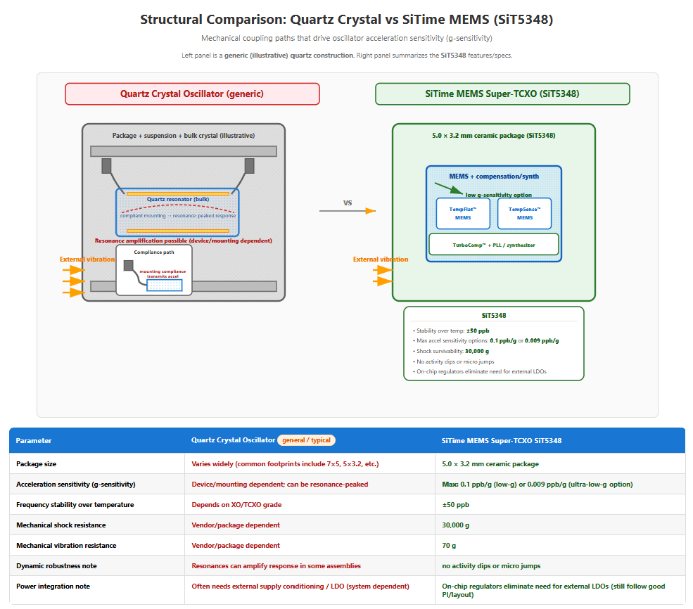
When a timing device experiences acceleration, mechanical forces act upon its resonating element. In traditional quartz crystal oscillators, the crystal blank, a precisely cut piece of piezoelectric quartz, undergoes microscopic deformation under acceleration. This deformation alters the mechanical resonance frequency, which directly manifests as a change in the output electrical frequency.
It is common to express g-sensitivity as Γ in ppb/g. In that case the fractional frequency error in ppb is: (Δf/f₀)_ppb = Γ · a
and the dimensionless fractional error is: Δf/f₀ = Γ · a · 10⁻⁹. Mathematically:
Δf/f₀ = Γ x a
Where:
For a 100 MHz oscillator with Γ = 1 ppb/g experiencing 10g acceleration, the frequency error would be: Δf = 100 MHz x 1x10⁻⁹ x 10 = 1 Hz
While 1 Hz may seem negligible, consider that in a GPS receiver maintaining carrier-phase tracking, or in a radar system performing coherent integration, such errors accumulate rapidly and degrade performance.
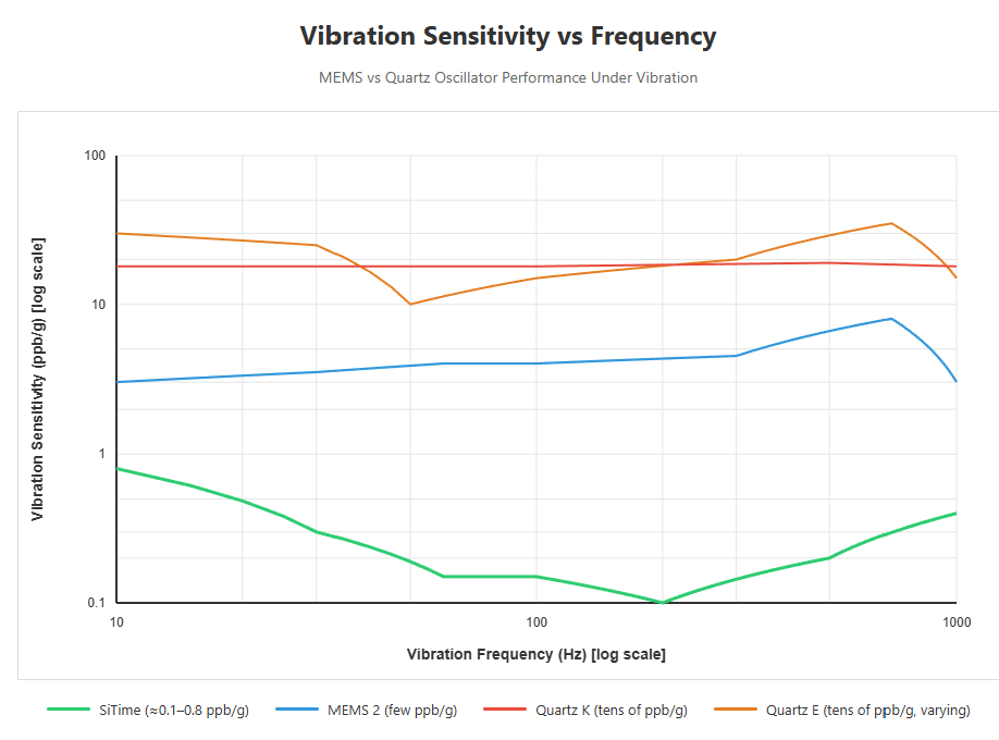
Vibration, unlike single-axis shock, involves periodic acceleration across a spectrum of frequencies. The vibration sensitivity of an oscillator is frequency-dependent because mechanical resonances in the crystal mounting structure, package, and PCB can amplify specific vibration frequencies.
The portfolio-level improvement factors cited here (e.g., 4× better vibration, 20× better shock survivability, 50× better g-sensitivity, programmable 1 Hz to 725 MHz) are stated in SiTime’s Silicon MEMS Timing Solutions overview.
Shock events, sudden, high-amplitude accelerations lasting milliseconds, present a different challenge. During shock, the instantaneous frequency error can be large, but of greater concern is the post-shock recovery behavior.
Quartz oscillators can exhibit dynamic disturbances under shock/vibration (e.g., amplitude/phase disturbances, and in severe cases activity dips or mode changes). SiTime positions its MEMS oscillators as offering strong dynamic stability and ‘no activity dips’ in harsh environments.
This translates to substantially improved shock robustness versus quartz (SiTime offers 20x better shock survivability at the portfolio level), which is valuable for applications exposed to severe mechanical shock (e.g., crash sensing, ruggedized avionics, drop-tested electronics).
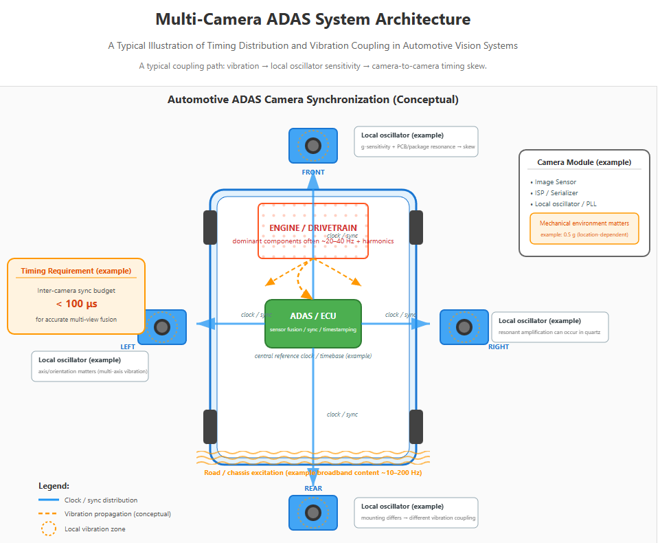
Modern vehicles deploy multiple cameras for surround-view systems, lane departure warning, and autonomous driving functions. These cameras must maintain frame synchronization within microseconds to enable accurate 3D reconstruction and object tracking algorithms.
Consider a typical automotive scenario:
If each camera uses an oscillator with Γ = 2 ppb/g and experiences 0.5g vibration at its resonant frequency, the frequency error per oscillator is: Δf/f₀ = 2 ppb/g x 0.5g = 1 ppb = 1x10⁻⁹
For a 27 MHz pixel clock, the absolute frequency shift is: Δf = 27 MHz · 1x10^-9 = 27 mHz
The corresponding time error after t seconds is approximately: Δt ≈ (Δf / f0) · t
For (Δf / f0) = 1x10^-9 and t = 1 s: Δt ≈ 1 ns
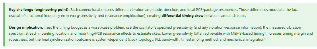
While 1 ns of time error per second (for 1 ppb fractional error) may seem small, real vehicle vibration is time-varying and multi-axis. Each camera module can see different acceleration amplitudes, orientations, and PCB/package resonances, so the instantaneous fractional frequency error Δf/f_0will differ between modules and can be periodically amplified near mechanical resonance. The resulting differential timing skew between cameras is therefore not a single constant number; it can fluctuate (and, in worst cases, grow enough to stress tight synchronization budgets), which is why low g-sensitivity and a flat vibration response are critical.
The simple Γ·a calculation illustrates instantaneous fractional frequency sensitivity, but the dominant system risk is often phase modulation/jitter (and, under shock, potential clock disturbances), not slow accumulation to microsecond-scale offset.
In systems that require sub-microsecond alignment, designers should budget skew using the worst-case specified g-sensitivity, the measured vibration spectrum at each camera location, and any resonance amplification of the mounted oscillator/PCB.
SiTime's SiT9386/87 automotive-grade oscillators specify operation across -40°C to +105°C with AEC-Q100 qualification. When paired with the ultra-low g-sensitivity of SiTime's MEMS technology (0.1 ppb/g typical, >10x better than quartz), the same 0.5g vibration produces only: Δf/f₀ = 0.1 ppb/g x 0.5g = 0.05 ppb
Frequency error: Δf = 27 MHz · 0.05x10^-9 = 1.35 mHz
Fractional error: Δf / f0 = 0.05x10^-9 = 5x10^-11
After 1 s: Δt ≈ (Δf / f0) · 1 s = 5x10^-11 s = 50 ps
This ~20x reduction in g-sensitivity provides significantly more timing margin, helping maintain camera synchronization even under harsh vibration and aggressive driving conditions.
In aerospace applications, timing accuracy affects navigation precision, radar coherence, and communication link stability. Military aircraft, helicopters, and UAVs (unmanned aerial vehicles) experience particularly severe vibration environments.
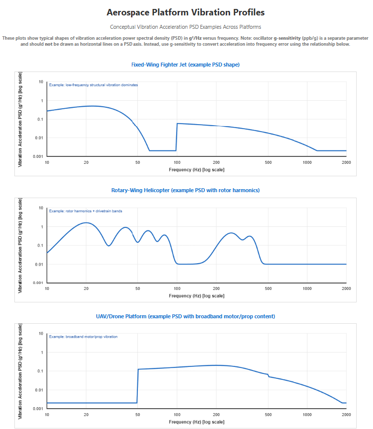
Because oscillator g-sensitivity Γ (units ppb/g) is not the same quantity as PSD (g²/Hz), it should not be plotted as horizontal lines on the PSD axis. Instead, PSD is used to estimate RMS acceleration, a_rms=√(∫PSD_a (f)" " df), and then map acceleration to fractional frequency error using (Δf/f_0 )_rms≈Γ" " a_rms⋅10^(-9) ┤.
Rotor-frequency note: for a helicopter at 300 RPM, the shaft frequency is 5 Hz, while the blade-pass frequency is 5" Hz"×N_"blades" (e.g., 20 Hz for a 4-blade rotor).
For precision navigation systems using GPS/INS (Inertial Navigation System) sensor fusion, the oscillator provides the time base for:
Vibration-induced frequency modulation appears as apparent Doppler shift in GPS receivers, degrading carrier-phase tracking and positioning accuracy. In military applications requiring precision targeting or autonomous landing, this degradation is unacceptable.
SiTime's aerospace-qualified oscillators meeting MIL-PRF-55310 standards, such as the SiT5348/49 Super-TCXO series, specify g-sensitivity of 0.004 ppb/g, among the lowest in the industry. This represents a 50x or more improvement over typical quartz oscillators, enabling maintained navigation accuracy even during extreme maneuvers.
High-precision industrial robots used in semiconductor manufacturing, surgical robotics, and automated assembly require position control accuracy at the micrometer scale. The servo control loops regulating motor currents operate at kHz rates, with timing derived from local oscillators.
During rapid acceleration (robot arm repositioning), the robot structure experiences vibration at natural mechanical frequencies (typically 50-200 Hz for industrial robot arms). If the servo controller's timing reference is sensitive to vibration, the control loop timing becomes inconsistent, introducing position errors.
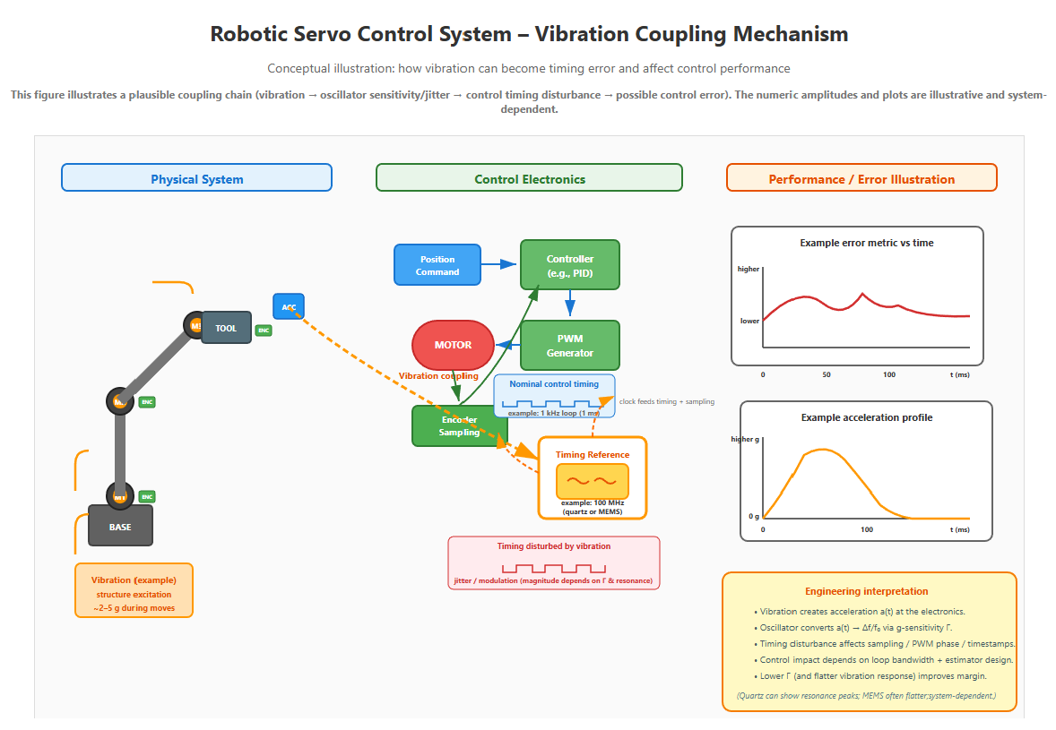
Performance illustration (right): example plots show that the acceleration transient can coincide with increased control error metrics; the exact magnitude depends strongly on loop bandwidth, estimator design, sampling strategy, mechanical resonances, and the oscillator’s vibration response.
The engineering message is that lower Γ (and a flatter vibration response) generally improves timing robustness and control margin, but the system outcome is application-dependent.
Using MEMS oscillators with 0.1 ppb/g sensitivity reduces timing jitter by 10x, improving servo control stability and final positioning accuracy.
SiTime's MEMS (Micro-Electro-Mechanical Systems) oscillators employ silicon resonating structures fabricated using semiconductor manufacturing processes. Unlike quartz crystals, which are discrete components assembled into packages, MEMS resonators are monolithically integrated with control electronics on a single silicon die or tightly coupled in a compact package.
Key structural advantages include:
SiTime's product portfolio includes several oscillator families optimized for high-vibration environments:
SiT5346/47/48/49 - Super-TCXO Series (Aerospace & Defense)
This specification of 0.004 ppb/g represents exceptional performance. For comparison, a high-quality quartz TCXO typically specifies 0.5-2 ppb/g, making SiTime's MEMS devices 125x to 500x better.
SiT9386/87 - Automotive Low-Jitter Oscillator
The SiT9386/87 combines low phase noise with mechanical robustness, making it ideal for automotive Ethernet, ADAS processing, and infotainment systems where both timing precision and vibration immunity are required.
SiT8924/25 - Automotive Standard Oscillator (AEC-Q100)
The availability of SOT23-5 packaging is particularly significant for automotive applications. If post-solder optical inspection is a requirement, SiTime highlights SiT2024/25 in SOT23-5 (leaded, not QFN) for easier post-solder optical inspection.
When designing for high-vibration environments, engineers should:
Even oscillators with excellent intrinsic g-sensitivity can experience degraded performance if improperly mounted:
Vibration can induce aerodynamic heating in high-speed applications (aerospace) or frictional heating in robotic joints. Oscillators with poor temperature coefficients will exhibit combined temperature and vibration-induced frequency drift.
SiTime's Super-TCXO products (SiT5155/56/57, SiT5356/57, SiT5358/59) offer exceptional temperature stability (±0.05 to ±2.5 ppm over the full operating range) while maintaining the same mechanical robustness as standard oscillators. This combination ensures frequency stability even when thermal and mechanical stresses occur simultaneously.
Based on data presented in SiTime's product documentation, the performance advantages can be quantified*:
*As positioned in SiTime’s portfolio overview.
These improvements translate directly to system-level benefits:
Note that the quantitative comparison plot and portfolio-level improvement factors cited in this article (e.g., 4x better vibration, 20x better shock survivability, 50x better g-sensitivity, programmable 1 Hz to 725 MHz) are taken from the SiTime ‘Silicon MEMS Timing Solutions’ overview.
Shock and vibration represent underappreciated threats to timing accuracy in modern electronic systems. As applications push into increasingly harsh environments, from autonomous vehicles navigating off-road terrain to UAVs operating in turbulent atmospheric conditions, the mechanical resilience of timing components becomes as critical as their electrical specifications.
SiTime Corporation's MEMS-based oscillator technology fundamentally addresses these challenges through:
Successfully implementing vibration-immune timing systems in automotive, aerospace, and industrial applications demands more than component selection, it requires deep understanding of oscillator physics, mechanical stress analysis, and system-level timing architecture. As a leading Nordic distributor of precision timing solutions, our technical team brings proven expertise to support your most demanding timing challenges.
Our Engineering Support Capabilities Include:
Explore SiTime Resources & Technical References:
📄 Application Notes & White Papers
This article is published for promotional and educational purposes by SAGA Components, an authorized distributor of SiTime Corporation products. Technical discussions are based on publicly available datasheets, industry standards for vibration testing (such as MIL-STD-810, IEC 60068-2-6, and AEC-Q100), and fundamental principles of oscillator design. Specific device architectures and proprietary technologies, including but not limited to SiTime's DualMEMS™ temperature sensing, TempFlat™ MEMS architecture, and EpiSeal™ encapsulation processes, are intellectual property of SiTime Corporation and are not disclosed in detail in this article. The performance comparisons presented represent typical industry values for conventional quartz devices and published specifications from SiTime datasheets; actual performance varies by manufacturer, part number, and operating conditions.