
Modern electronic systems face unprecedented thermal challenges as component density increases and power consumption escalates. The relentless pursuit of miniaturization, combined with higher performance requirements, creates complex thermal management scenarios where traditional passive cooling approaches fall short. Active thermal management through precisely engineered airflow distribution has become essential for maintaining optimal operating temperatures and ensuring system reliability.
At SAGA Components, we combine deep thermal engineering expertise with the comprehensive axial fan range from Cainton Corporation to deliver cooling solutions tailored to the most demanding applications.
The fundamental challenge lies in efficiently removing heat from multiple sources within confined spaces while maintaining acceptable noise levels and power consumption. This requires a deep understanding of heat transfer mechanisms, fluid dynamics, and the careful selection of cooling components that can deliver optimal performance under specific operating conditions.
Electronic components generate heat through various mechanisms, primarily Joule heating in resistive elements and switching losses in semiconductors. The heat removal process involves three fundamental modes of heat transfer that must be optimized in any cooling design:
Figure 1: Heat Transfer Mechanisms Diagram. The diagram illustrates conduction through heat spreaders, convection around components, and radiation between surfaces, with heat flow arrows and temperature gradients.
Heat conduction through solid materials follows Fourier's law:
Fourier's Law (Conduction): q = -kA(dT/dx)
Where:
• q = heat transfer rate (W)
• k = thermal conductivity (W/m·K)
• A = cross-sectional area (m²)
• dT/dx = temperature gradient (K/m)
For multi-layer electronic assemblies, thermal resistance networks become complex, requiring careful analysis of interface resistances and material properties.
Forced convection, achieved through axial fan-driven airflow, follows Newton's law of cooling: q = hA(Ts - T∞)
Where:
• h = convective heat transfer coefficient (W/m²·K)
• A = surface area exposed to airflow (m²)
• Ts = surface temperature (K)
• T∞ = ambient air temperature (K)
The heat transfer coefficient h is strongly dependent on airflow velocity, fluid properties, and surface geometry, making fan selection critical for thermal performance.
At elevated temperatures, radiation becomes significant: q = εσA(Ts⁴ - T∞⁴)
Where:
• ε = surface emissivity
• σ = Stefan-Boltzmann constant
Where ε is surface emissivity and σ is the Stefan-Boltzmann constant.
Modern thermal management relies heavily on computational fluid dynamics (CFD) to predict and optimize airflow patterns within electronic enclosures. The governing equations for fluid flow include the continuity equation and Navier-Stokes equations:
Continuity Equation: ∂ρ/∂t + ∇·(ρv) = 0
Navier-Stokes Equations: ρ(Dv/Dt) = -∇p + μ∇²v + ρg
These equations, when solved numerically, provide detailed velocity and pressure fields that enable engineers to identify flow recirculation zones, stagnation points, and optimal fan placement locations.
Figure 2: CFD Airflow Pattern. A 3D CFD simulation showing airflow streamlines, velocity vectors, and pressure contours within a typical electronics enclosure with multiple heat sources and fan placement options.
Axial fans operate according to well-defined performance curves that relate volumetric flow rate to static pressure rise. The fan performance is characterized by: Pfan = Q × ΔPstatic
Where:
• Pfan = fan's hydraulic power output
• Q = volumetric flow rate
• ΔPstatic = static pressure rise
Figure 3: Fan Performance Curves. A comprehensive chart demonstrates the static pressure vs. airflow curves for different Cainton fan models (30mm to 172mm), with system resistance curves and operating point intersections.
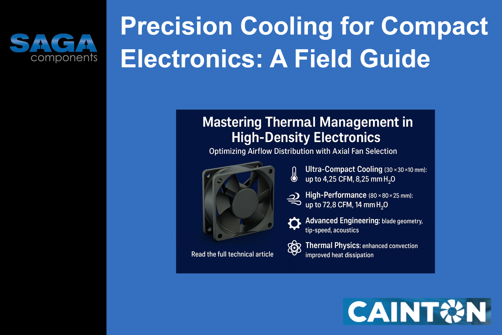
Cainton Corporation offers an extensive range of axial fans specifically designed for electronics cooling applications. Their product line spans from ultra-compact 30x30x10mm units suitable for embedded applications to large 172x150x55mm fans for high-airflow server cooling.
The AXD3010 series represents the pinnacle of miniaturization in axial fan technology. Operating at voltages from 5V to 12V, these fans deliver airflow rates from 0.98 to 4.25 CFM while maintaining static pressures up to 8.25 mmH2O. The plastic housing with UL94V-0 flammability rating ensures safety in dense electronic assemblies.
Key Performance Parameters:
• Speed range: 5,000-13,000 RPM
• Power consumption: 0.72-1.2 W
• Noise levels: 15.5-34.9 dB(A)
• Operating temperature: -40°C to 90°C
The AXD4010 and AXD6025 series provide enhanced airflow capacity for medium-density applications. These fans incorporate advanced blade geometries optimized for static pressure applications, crucial for cooling components behind heat sinks or within restricted flow paths.
The 60x60x25mm B-Type fans (AXD6025V12XL-K2 through AXD6025V12HX-K2) demonstrate remarkable versatility, with airflow ranging from 15.6 CFM at 3,000 RPM to 39.5 CFM at 7,500 RPM, while maintaining static pressures from 2.92 to 16.83 mmH2O.
For demanding thermal management applications, Cainton's larger fans provide exceptional performance. The 80x80x25mm E-Type series (AXD8025V12LW-K5 through AXD8025V12HH-K5) delivers airflow rates up to 72.8 CFM with static pressures reaching 14 mmH2O.
Figure 4: Temperature Distribution Comparison. A side-by-side thermal simulation results displaying temperature distributions in a server blade with and without optimized Cainton fan cooling.
The flagship 172x150mm series offers industrial-grade performance with the AXA17255V1HBM-L2 delivering 293 CFM at 3,300 RPM with 20 mmH2O static pressure capability. These fans utilize aluminum alloy housings with metal impellers for maximum durability and heat resistance.
Electronic system cooling design requires careful matching of fan characteristics to system resistance. The system resistance curve typically follows: ΔPsystem = K × Q²
Where:
• K = system resistance coefficient
• Q = volumetric flow rate
The intersection of the fan curve and system resistance curve determines the actual operating point:
Fan Curve: ΔP = f(Q) = a₀ + a₁Q + a₂Q² System Curve: ΔP = K × Q² Operating Point: f(Q) = K × Q² → Qoperating
System Coefficient Calculation: K = ΔP / Q²
Figure 5: Operating Point Analysis. The chart shows the intersection of fan performance curves with various system resistance curves, highlighting how different Cainton fan selections affect operating points and thermal performance.
Noise generation in axial fans primarily results from turbulent flow around blade edges and pressure fluctuations. The relationship between tip speed and noise, as a rule-of-thumb, follows: SPL ∝ Vtip⁵ to Vtip⁶
Where:
• SPL = sound pressure level
• Vtip = blade tip velocity
Cainton's fans are engineered with optimized blade profiles that minimize noise while maintaining performance, with many models operating below 35 dB(A).
Modern electronic systems demand energy-efficient cooling solutions. The fan efficiency can be expressed as: ηfan = (Q × ΔPstatic) / Pelectrical
Where:
• ηfan = fan efficiency
• Pelectrical = electrical power input
Cainton's advanced motor designs achieve high efficiencies across their operating ranges, with precise current consumption specifications enabling accurate power budget calculations.
Ball bearing technology in Cainton fans provides superior reliability compared to sleeve bearings, with mean time between failures (MTBF) typically exceeding 50,000 hours at rated conditions. The wide operating temperature range (-40°C to 90°C for DC models) ensures reliable operation across diverse environmental conditions.
Figure 6: Fan Size and Performance Comparison. The comprehensive comparison graph exhibits Cainton's complete fan range with size, airflow, static pressure, and power consumption metrics.
High-density server applications require fans capable of overcoming significant static pressure from densely packed components and narrow air channels. Cainton's 80x80x25mm E-Type fans excel in these applications, providing the high static pressure necessary for effective cooling while maintaining reasonable noise levels.
Space-constrained embedded applications benefit from Cainton's ultra-compact 30x30x10mm series. These fans enable active cooling in applications previously limited to passive solutions, significantly improving thermal performance in miniaturized designs.
The 172x150mm series with aluminum housings provides robust cooling solutions for industrial electronics operating in challenging environments. The metal construction ensures durability while the high-temperature rating supports operation in elevated ambient conditions.
Optimal fan placement requires consideration of:
• Proximity to heat sources
• Airflow path obstruction
• Pressure drop minimization
• Acoustic isolation requirements
Modern thermal management systems benefit from intelligent fan control. Cainton's PWM-compatible models (N3, N5, N6 functions) enable precise speed control based on thermal feedback, optimizing both cooling performance and energy consumption.
Effective cooling system design must address thermal interfaces between heat sources and airflow paths. High-quality thermal interface materials, combined with optimized fin geometries, maximize the effectiveness of Cainton's fan-driven cooling solutions.
Effective thermal management in high-density electronics requires sophisticated understanding of heat transfer mechanisms, fluid dynamics, and precise component selection. Cainton Corporation's comprehensive axial fan range provides engineers with the tools necessary to address diverse cooling challenges, from ultra-compact embedded applications to high-performance server environments.
The key to successful thermal design lies in the systematic analysis of heat generation, airflow requirements, and system constraints, followed by careful selection of fans that provide optimal performance at the required operating points. Cainton's detailed performance specifications, combined with advanced design features such as ball bearing reliability and wide operating temperature ranges, enable engineers to develop robust cooling solutions that meet the demanding requirements of modern electronic systems.
As electronic systems continue to evolve toward higher power densities and more compact form factors, the role of precisely engineered thermal management becomes increasingly critical. The combination of computational design tools, comprehensive performance data, and high-quality cooling components provides the foundation for successful thermal management in the next generation of electronic systems.
Mastering thermal management challenges in high-density electronics requires specialized knowledge of heat transfer, airflow dynamics, and precise fan selection. At SAGA Components, our thermal engineering specialists, supported by our strategic partnership with Cainton Corporation, deliver comprehensive cooling solutions. We help you:
• Analyze thermal requirements and translate heat dissipation needs into optimal fan specifications
• Evaluate Cainton's complete product range against system constraints, emphasizing performance and efficiency advantages
• Coordinate supply chain logistics and ensure availability for high-volume manufacturing
Our extensive experience in thermal physics, fluid dynamics, and electronics cooling standards empowers us to support your entire development cycle—from initial thermal analysis through production qualification. By collaborating with SAGA Components and utilizing Cainton's advanced axial fan portfolio, you can achieve superior thermal performance, reliability, and cost-effectiveness in your most challenging cooling applications.
Contact: 📧 Email: contact@sagacomponents.com
📞 Phone: +46 (0) 8 564 708 00
🌐 Web: https://www.cainton.com/
#ThermalManagement #ElectronicsCooling #AxialFans #HeatDissipation #ThermalDesign #AirflowOptimization #CoolingEngineering #ElectronicsDesign #CaintonCorporation #ThermalEngineering #CFDModeling #FanSelection #HeatTransfer #ThermalSolutions #ComponentCooling #SAGAComponents #SystemThermals #NordicTech